Access : CP::Micrograph::Imaging Setup (Tab)
|
|
|
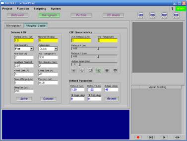
In single-particle EM data acquisition, protein specimens are often imaged by defocused beam to enhance the image contrast. As a result, the recorded image is modulated by a Contrast Transfer Function (CTF), which can be analytically modeled and corrected during data processing. Also, the tilting configuration of the specimen grid can be assessed by the defocus variation across the image plane. In PARTICLE, the Micrograph::Imaging Setup module provides the functions for image CTF and tilt-geometry determination.
In a simple form, CTF can be modeled with an analytical function parameterized by a triplet: {defocus-X, defocus-Y, astigmatic angle}. The following imaging parameters need to be defined in order to determine the CTF parameters:
After the imaging parameters have been properly defined, activate the Solve button to determine the CTF and tilt parameters of the image. Upon completion, the result will be displayed in the designated value-boxes at the Refined Parameters group. The Accept button will permanently enter the results to the CP::DataView spreadsheet in the project space.
Once determined, the imaging CTF and tilt parameters will be automatically incorporated into the subsequent data processing and no further action from the user is required for the CTF correction.
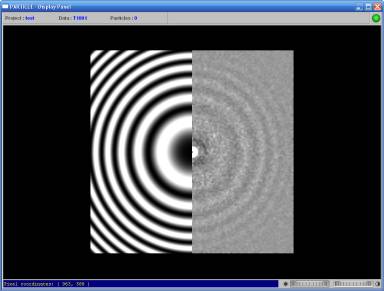
In PARTICLE, CTF patterns (a.k.a. Thon Rings) can be simulated from a set of user-defined imaging parameters for experimentation. Several display modes are available for visualizing an image power spectrum and its comparison with a theoretical CTF pattern: